TYPES OF PLANTS
Claus Sulfur Recovery Units are generally classified according to the method used for the production of SO2 and the method used to reheat the catalyst
bed feeds. The various reheat methods can be used with any SO2 production method, whereas the technique used for the production of SO2 is determined by the H2S content of the acid gas feedstock. Most sulfur recovery plants utilize one of three basic variations of the Modified Claus Process “straight-through,” “split-flow,” or “direct-oxidation.”Acid gas enrichment” can be applied ahead of the SRU to produce a richer acid gas stream and “oxygen enrichment” may be used in combination with any of these variations.
These three varieties of the Modified Claus Process differ in the method used to oxidize H2S and produce SO2 ahead of the first catalytic reactor. The first two processes use a flame reaction furnace ahead of the catalytic stages. The third process reacts oxygen directly with the H2S in the first catalytic reactor to produce the SO2.
Straight-Through Process
A “straight-through” unit (shown in Figure 2) passes all the acid gas through the combustion burner and reaction furnace. The initial free-flame reaction usually converts more than half of the incoming sulfur to elemental sulfur. This reduces the amount which must be handled by the catalytic sections and thus leads to the highest overall sulfur recovery. The amount of heat generated in the reaction depends on the amount of H2S available to the burner. With rich acid gas (60% - 100% H2S), the reaction heat keeps the flame temperature above 2200°F. When the gas is leaner, the flame temperature is reduced; the greater mass is heated to a lower temperature. If the temperature falls below a critical point, approximately 1800°F to 2000°F, the flame becomes unstable and cannot be maintained. This point is usually reached when the acid gas has an H2S content of 50% or less. The problem can be overcome, within limits, by preheating the acid gas and/or air before it enters the burner. However, the lower the H2S content, the higher the preheat requirement becomes; when the gas composition falls below about 40% H2S, this approach ceases to be practical.
Split-Flow Process
The second method of SO2 production, known as the “split-flow” technique, is used to process leaner acid gases with 15% to 50% H2S content. In these units, at least one-third of the acid gas flows into the combustion burner and the balance usually bypasses the furnace entirely. Enough H2S is burned to provide the necessary 2:1 ratio of H2S to SO2 in the catalyst beds. The flame temperature is kept above the minimum since the constant amount of heat supplied is absorbed by a lower mass of gas. The free-flame Claus reaction is reduced or eliminated entirely by this approach since little or no H2S is available to react in the furnace. This results in a slight reduction in the overall sulfur recovery.
Split-Flow Process For Ammonia Destruction
A variation of the split-flow process is often applied in refinery SRU’s that must process sour water stripper (SWS) off-gas and destroy the ammonia it contains. Efficient ammonia destruction is critical for SRU’s in refineries since ammonia can combine with the sulfur compounds in the process gas to form salts that precipitate in the lower temperature section of the Claus unit. Accumulation of such ammonium salts would lead to unreliable operation and unacceptable maintenance costs. Figure 2 shows the special split-flow furnace design used when processing SWS gas along with acid gas from an amine unit. All of the SWS gas is routed to the combustion burner along with a portion of the amino acid gas so that at least 1/3 of the total H2S is supplied to the burner. This creates a high-temperature combustion zone at the inlet end of the reactor furnace where the ammonia breaks down into nitrogen and water by thermal decomposition. The remainder of the amino acid gas is injected into the middle part of the reactor furnace where it mixes with the burner combustion products. The outlet end of the
furnace provides residence time for the SO2 produced by the burner to react with the H2S in the bypass acid gas and form sulfur, and for any hydrocarbons in the bypass acid gas to oxidize. An optical pyrometer is typically used to monitor the temperature in the inlet section of the furnace and is often used to adjust the amount of bypass acid gas to control the temperature at the desired value.
Direct Oxidation Process
When the H2S concentration is below about 15% in the acid gas, the direct oxidation version of the Modified Claus Process may be used. Rather than using a burner to combust H2S to form SO2, the direct oxidation process catalytically reacts oxygen with H2S by mixing the air and acid gas upstream of a catalytic reactor. As SO2 forms, it then reacts with the remaining H2S via the Claus reaction to form sulfur. The direct oxidation is typically followed by one or more standard Claus reactors to produce and recover additional sulfur. The direct oxidation process is sensitive to catalyst deactivation by contaminants in the acid gas feed (particularly hydrocarbons), so it is not used as much as the other Claus process varieties.
Acid Gas Enrichment
When the acid gas produced by the gas treating system is low in H2S concentration, it is sometimes advantageous to “enrich” the acid gas by contacting it with a second solvent. The second solvent is typically a selective solvent designed to absorb essentially all of the H2S from the acid gas while letting most of the remainder (generally carbon dioxide, CO2) “slip” through. The enriching process can often raise the H2S concentration of the SRU feed gas by a factor of 5 or more. Not only does this allow using smaller equipment in the SRU, but it can often allow a more reliable SRU process to be used, such as a straight-through Claus Process instead of a direct oxidation Claus process.
Oxygen Enrichment
Since air is approximately 79% nitrogen and 21% oxygen, the introduction of air to supply the oxygen for combustion of H2S to SO2 also introduces a
a large quantity of nitrogen. When air is used as the oxygen source, approximately 5.6 moles of nitrogen are introduced into the gas flow for every mole of H2S that is burned. Nitrogen does not react and the added mass of the nitrogen lowers the adiabatic flame temperature in the reaction furnace. The nitrogen must also be heated, cooled and reheated through the combustion, sulfur condensation, and reheat ahead of the reactors. Pure oxygen or enriched sources of oxygen can be used instead of air in the Claus Process. Higher flame temperatures can be achieved with lower H2S concentrations. In addition, the relative equipment sizes can be reduced in proportion to the amount of nitrogen that is not introduced with oxygen for combustion.
Reheat Methods
The gas leaving the sulfur condenser is at its sulfur dew point temperature. Since the catalytic reaction requires a higher temperature for proper operation, the gas must be reheated before entering the reactor. This can be done directly (internally) or indirectly (externally). The method chosen is an important characteristic of any Sulfur Recovery Unit.
Direct Reheat
Two direct reheat methods are commonly employed: “inline burning” and “hot gas bypass.” The first of these burns fuel or acid gas with air in an inline burner, allowing the combustion products to mix directly with the process gas flow. The second method bypasses a portion of the hot boiler outlet gas around the sulfur condenser and mixes it with the reactor feed stream. Both methods have an adverse effect on overall sulfur recovery. In the case of the inline burner, it is difficult to maintain precise control of the overall air/ H2S ratio. Any excess of deficiency of oxygen to the inline burner can cause undesirable reactions in the catalyst beds. Too little oxygen can lead to carbon deposits on the catalyst, reducing its activity. Too much oxygen can lead to catalyst deactivation, increased corrosion and, in extreme cases, fire in the reactor. All of these result in reduced sulfur recovery. The “hot gas bypass” method allows a portion of the sulfur-bearing process gas to skip one or more catalytic reactions and sulfur condensing steps. When this happens, the sulfur gases have less opportunity to convert to sulfur vapor and the overall sulfur recovery drops. With both methods, the recovery loss is more pronounced in a lean acid gas unit than it is in a rich gas SRU.
Indirect Reheat
The indirect reheat method uses an outside heat source to raise the temperature of the acid gases in a heat exchanger. Although this requires additional equipment, it eliminates the conversion loss problems associated with direct reheat. There are three common variations of indirect reheat: “gas-gas exchange,” “fuel gas firing,” and “steam reheat.” Gas-gas exchangers use sulfur condenser feed to reheat the sulfur condenser outlet gas. This exchange works well as long as the temperature of the heating gas is maintained above a minimum level. If the upstream catalyst bed has lost some of its efficiency, however, the drop in conversion will lower the outlet temperature. Less heat energy will be available for reheat. As a result, the following catalyst bed will perform less efficiently and overall sulfur recovery will decrease.
Steam reheat and fuel gas-fired heaters have none of the problems associated with the gas-gas exchange method above. Fuel gas firing uses a conventional fired heater; the acid gases are heated in tubes and the combustion products are vented to the atmosphere. For this reason, fuel gas firing usually involves higher utility costs than the other indirect methods. Steam reheat can usually be accomplished by utilizing a portion of the steam produced by the SRU itself, often in the same vessel with the source of steam production. Steam reheat is the method commonly preferred in better quality sulfur plant designs.
Recovery and Emissions Levels
Most Sulfur Recovery Units are installed to meet mandated air pollution requirements. The U.S. Environmental Protection Agency (EPA) has issued standards for acceptable emissions from new and modified SRU’s in natural gas production. Under these standards, the volume of H2S concentration of the acid gas stream determines the minimum sulfur recovery level required. Small natural gas SRU’s with low H2S concentrations are allowed to have lower recovery levels than larger plants with higher concentrations. The chart in Figure 3 shows these mandated recovery levels as a function of total sulfur and H2S concentration in the acid gas to be processed. Also shown in Figure 3, as the plant size and H2S concentration increase, the required recovery level begins to exceed what can be accomplished with just a Claus SRU. This will normally require the addition of a tail gas cleanup process downstream of the Claus SRU.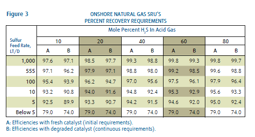
Tail Gas Cleanup
If a three-stage or four-stage Sulfur Recovery Unit cannot meet the minimum EPA recovery levels, further processing is required. This involves a Tail Gas Cleanup Unit (TGCU), which can either be integrated with the SRU at the design stage or added to an existing SRU. Tail Gas Cleanup Units are divided into two general types: dry bed processes and wet scrubbing processes. Dry bed processes such as the Amoco Cold Bed Adsorption (CBA) process use the same catalytic Claus reaction as the standard SRU, except that they are operated below the sulfur dew point temperature. As the sulfur forms, it is deposited on the catalyst. Once the catalyst bed has adsorbed a sufficient quantity of sulfur, it is regenerated to strip the sulfur from the catalyst and recover it. This type of process can achieve an overall sulfur recoveries of 99.0% or better. Wet scrubbing processes, such as the Shell Claus off-gas Treating (SCOT) process, including a front-end section to convert all of the sulfur compounds in the SRU tail gas back into H2S. After cooling, the H2S-containing process gas is contacted with a solvent to remove the H2S, much like in a conventional gas treating plant. The solvent is then regenerated to strip out the H2S, which is then recycled to the upstream SRU for subsequent conversion and recovery. This type of process can achieve overall sulfur recoveries of 99.9% or better and can reduce the sulfur emissions to less than 250 ppm in the incinerator effluent.